
DIO vs GPIO? Key Differences for IIOT Gateways and Edge Computing
With the fourth industrial revolution upon us, a combination of powerful AI computers, energy efficient IIoT ‘Industrial Internet of Things’ Gateways, and remote IIoT devices are being deployed at the edge for interconnecting machines and sensors. Both GPIO (General Purpose Inputs & Outputs) and DIO (Digital Inputs and Outputs) play a key role in connecting edge devices and sensors in the quickly-evolving Industrial Internet of Things model. Allowing for both local and remote management of systems and devices, Digital I/O helps play a significant role in ensuring effective communication between systems and their operators.
Implementing industrial-grade edge computing allows the process of data at the ‘edge,’ or periphery, close to the originating source. Benefits of capturing and processing data at the source rather than relying on cloud computing includes increased decision making speed with lower latency, higher system reliability with continued operation and optimisation, and lower operational costs as fewer data centres are required to process smaller amounts of data.
As part of Industry 4.0, machine learning models are implemented on devices at the edge to improve the effectiveness of operations through self-learning. This acceleration of dynamic system process optimisation, or Smart Automation, is a step up from simple logic-based control and can help deliver real impact in operational efficiency and innovation.
With a wide range of embedded box computers, single board computers, and industrial motherboards supporting local GPIO and DIO we will discuss key differences with the abilities for both onboard and remote expansion.
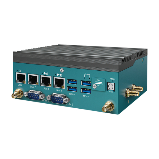
Industrial-Grade Computing Supporting GPIO & DIO Onboard
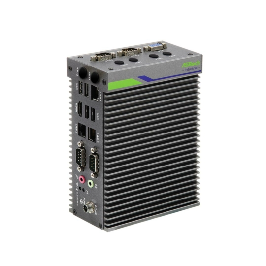
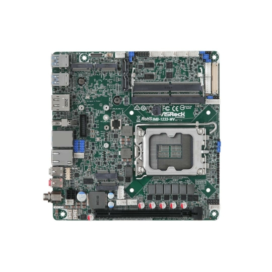
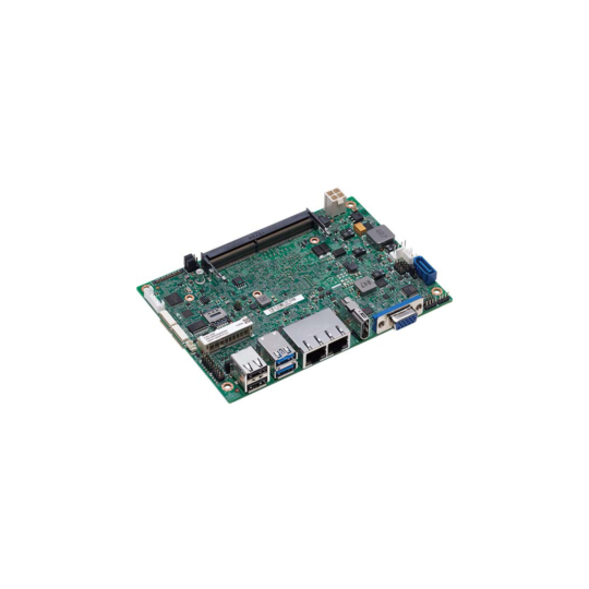
Industrial Automation PCs
What is GPIO? General Purpose Inputs and Outputs
General Purpose Input Output, commonly known as GPIO, is a programmable interface that lets embedded controllers send and receive digital signals from IoT sensors, transducers, actuators etc. Despite its name, general purpose refers to the applications for digital signal interface only, they can not be used for accepting analog signals comprising of varying voltages. GPIO pins are commonly used with push fit connectors for input and output channels and an electric current is required in order for them to function properly. The input allows the embedded PC to recognise the IoT device, and then relay command signals through the output. This transfer of information is known as logic signals. These logic signals have two possible values and in general would be represented as either ON or OFF. It is this simple ON/OFF configuration which means other complex protocol such as Serial or USB is not required. GPIO can connect multiple devices simultaneously and is only limited by the channel count and system performance. This means that it has an endless number of uses in general automation and is programmable to best suit the user’s operations.
What is DIO? Benefits of Isolating Digital Inputs and Outputs
DIO stands for Digital Input/Output. This interface allows an embedded computer system to send and receive digital signals to and from IoT connected devices an sensors. The embedded controller can be set up with automation software to have the control systems operate in a desired way so that input values control the desired outputs.
One of the most common examples of a digital input would be connecting various sensors. Sensors are used in a wide range of industries, with manufacturing and factory automation being the most common. Automation sensors can detect everything from the position of a robotic arm to the level of liquid in a tank. By reading these sensor signals, automation PCs configured with DIO can automatically adjust processes and improve efficiency via its digital outputs.
This likely is sounding very familiar to GPIO. DIO is the perfect solution for any environment where you need to eliminate electrical noise and isolate your signals. This includes places like manufacturing or industrial factory floors, where voltage spikes and ground loops may occur as well as common mode signals that can confuse your equipment’s electronics. The losses caused by corrupt data signals can be devastating. From halted operations, machinery malfunctions and worse of all damaged electronics it’s important that we isolate our signals for optimum efficiency.
The isolation technology in Digital I/O makes it perfect for use with industrial applications. The opto-isolation process uses lights to separate individual pins, physically and electrically from one another as well as all incoming signals coming into or leaving through its ports. These closed optical channels, called photocouplers, prevent any signal interference getting through and confusing your automation platform.
Summary of Differences Between DIO and GPIO
The main difference between DIO and GPIO is quite apparent in terms of isolation. While both GPIO and DIO can handle a similar channel count, DIO utilizes an isolation technique to maintain electrical integrity where as GPIO doesn’t. This additional layer of protection provided by isolated DIO can save machinery failure from electrical events if GPIO was used instead.
Another key difference to note is that GPIO pins are not sustainable on industrial factory floors or environments prone to shock and vibration. This can cause GPIO push fit pins to become loose or disconnected with the sensors or IIoT devices. DIO typically supports locking terminal blocks as a basic requisite and more industrial rugged computers will utilize locking circular M12 connectors for best practice in harsh environments. Maintaining a locked connector makes DIO not only more reliable but ideal for operator switches, machinery status signals and limit switches to name a few use cases.
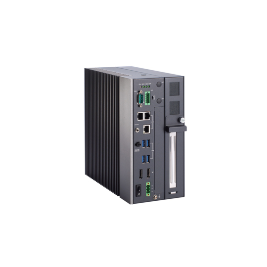
Expanding IIoT with DIO
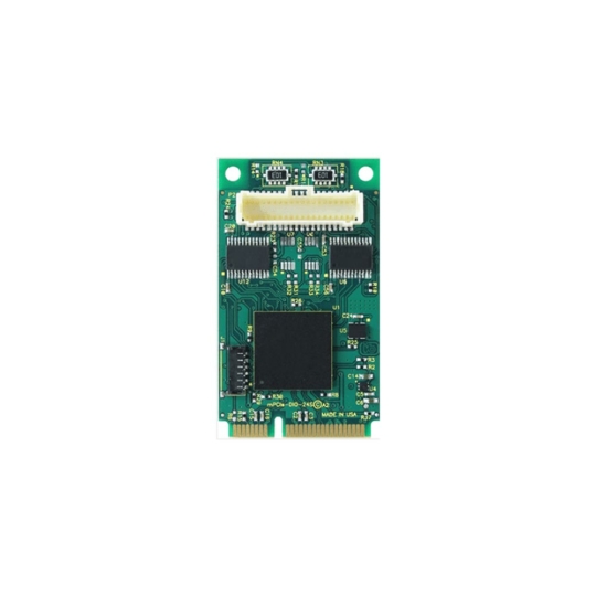
mPCIe DIO
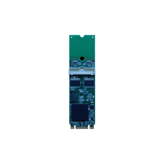
M.2 Expansion DIO
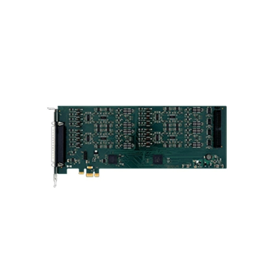
PCI & PCIe Expansion DIO
Wireless DIO
Ethernet DIO

USB DIO
Isolation DIO Technologies for Reliable Industrial Measurement & Control
Digital I/O can be expanding with local I/O or remote I/O. Local I/O refers to the inputs and outputs that are housed in the same cabinet and likely integrated with the rugged edge computer. Digital I/O can be expanded on our range of industrial PCs with a wide range of channel counts in different form factors. Board level solutions for integration inside an Industrial PC or as part of a single board computer stack are available in PCI, PCI Express, PC/104, mPCIe and M.2 form factors. Remote I/O simply means that the I/O, in most cases a DIN-mount module, is at a remote place physically located a distance from the IPC (Industrial PC). Here is a range of external DIO devices which can be connected to the Industrial PC via USB, Serial, Ethernet, or various Wireless protocols.
USB DIO: USB digital I/O modules connect to any embedded PCs USB port to provide optically isolated inputs. USB connectivity provides simplified installation for local control and reliable communication. Typically available in a chassis or as a stackable OEM board level solution.
Serial DIO: A common expansion for industrial automation allowing automation PCs to communicate via RS232/422/485 protocol both locally and remotely.
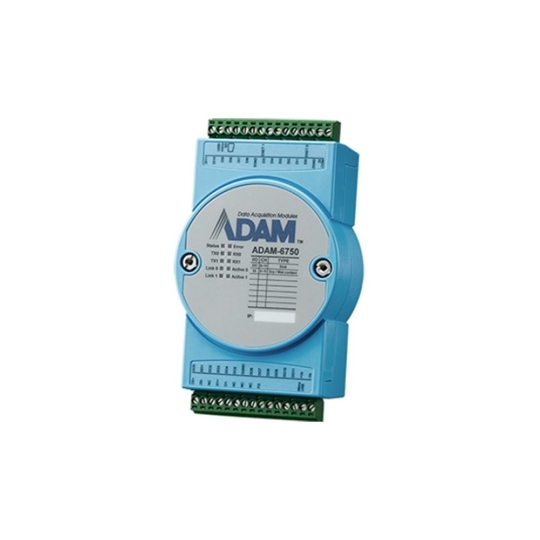
Ethernet DIO: Ethernet digital I/O devices are cost-effective and allow remote monitoring of digital signals from anywhere on your Ethernet network with 10/100 Base T Ethernet connectivity.
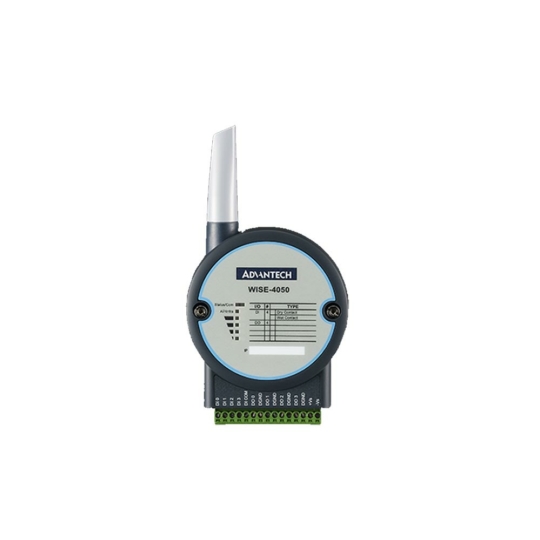
Wireless DIO: Wireless data acquisition devices provide powerful digital I/O in remote locations where network cables aren’t already present. Wireless DIO modules leverage Wireless Ethernet (WiFi/Bluetooth/Zigbee), Cellular (3G/LTE/CAT.NB1/CAT.M1), and ‘LPWAN’ Low-Power Wide Area Network (LoraWAN) technology to provide a robust wireless interface, easy installation and reliable communication.

Looking to Expand with Digital I/O?
Tell us about your application and a member of our team will get right back to you.