
Installing M.2 SSDs & Modules: Which Slot or Socket Should I Use?
Quickly becoming the common standard for onboard expansion in embedded and industrial computing, M.2 expansion is replacing the likes of mPCIe and mSATA for expansion and storage capabilities. The M.2 form factor was introduced into the market by Intel in 2015 as the Next Generation Form Factor (NGFF) and was adopted for numerous applications such as quicker read/write cycles on board SSD storage and adding basic wireless connectivity to devices. Using up to four lanes to communicate with the onboard CPU, transfer rates via the M.2 expansion slot are considerably faster when compared to onboard Mini PCIe or mSATA, which only utilize a single lane to communicate.
In this comprehensive guide we look at the technologies found onboard M.2 SSDs and M.2 expansion cards available in the market. This includes taking a look at key features which can determine compatibility and performance before installing on your next single board computer, industrial motherboard, embedded box PC, or industrial computer. We will also demonstrate how to install an M.2 SSD onboard a host embedded board.
A Brief on mPCIe & mSATA Legacy Technologies
Before M.2 came about the I/O throughput and data transfer standard was via mPCIe and mSATA architecture. Under first impression the mPCIe and mSATA cards can be very difficult to distinguish due to similarities in physical traits such as form factor and connector type. Both mPCIe cards and mSATA cards are available in full size and half size cards, full size cards measuring 30×50.95mm and half size cards measuring 30×26.8mm. Sharing the same form factor and connector means you can theoretically plug a mSATA card into a mPCIe slot or mPCIe card into a mSATA slot, but protocol is key to whether it works or not. The main difference between mini-PCIe and mini-SATA is the protocol. PCI Express is an expansion protocol for sending and receiving data signals through serial link connections in a single lane of PCIe signal. mSATA on the other hand is used for mechanical storage drives that support native command queuing through AHCI (advanced host controller interface) protocol to read and write data.
The Mini PCIe form factor was launched in 2002 as a versatile and compact expansion form factor which was originally designed to allow for connectivity peripheral cards such as Wi-Fi, Bluetooth, Cellular, SIM cards etc to be easily integrated into mobile computing platforms such as laptops and mobile devices. This quickly transitioned int0 the industrial marketplace and became an embedded standard across a wide range of box PCs and single board computing platforms due to similar space constraints and requirements for compact form factor designs. Although this is becoming a legacy expansion port, mPCIe is still widely utilized by industrial embedded computing manufacturers in combination with the new M.2 form factor.
mSATA was later introduced in 2011 and adopted the AHCI (advanced host controller interface) protocol to read and write data. This was a big advancement in storage expansion requirements in order to meet the demands for smaller and more compact SBCs such as the 3.5″ SBC and PICO-ITX board. Utilising SATA protocol as the logical communication interface, mSATA or mini-SATA SSDs made onboard storage capabilities physically possible and removed the need for 2.5″ HDD/SSD drive bays.
Albeit sharing the same form factor and connector type, not all embedded systems support mSATA and would only cater for PCIe or USB bus protocols for data communication. This means that a mSATA SSD would fit snugly into a mPCIe expansion bay but due to different electrical specifications being supported, it simply wouldn’t communicate. This is the same for mSATA slots only supporting SATA protocol and not PCIe or USB protocol for expansion with other mPCIe cards.
The main limitation which progressed the development of M.2 expansion by Intel was the bandwidth. Only supporting a single lane of PCI Express or AHCI interface the maximum bandwidth is capped. To increase this bandwidth under the PCIe standard more lanes were required to communicate and increase the bandwidth for both sending and receiving signals. This paved the way for SSDs utilising the PCIe protocol.
What is M.2?
M.2 expansion is the most recent standard for compact internal expansion cards integrated on a motherboard. In summary, the M.2 next generation form factor is providing faster and more flexibility with storage and a wide range of expansion cards than its mPCIe and mSATA predecessor. The new M.2 interface supports multiple data rates and uses an upgraded signalling interface, resulting in improved performance, reduced software overhead, and increased system reliability.
Benefits of M.2 Expansion
The advanced technology of M.2 expansion offers high-speed bandwidths, enhanced power efficiency, and a space-saving compact design, making it suitable for a broad spectrum of embedded computing applications. Below you’ll find the benefits of M.2 SSDs and other type of expansion cards, with a more detailed explanation provided further down on why they are worth using.
High Speed Technology: M.2 modules with PCIe 4.0 support can transfer data much faster, up to 16Gb/s per lane with a maximum of 4x lanes supported. M.2 NVMe SSDs are also blazingly fast when compared to traditional SATA SSDs, up to 650% faster. Supporting high-speed data transfer and storage capabilities, M.2 expansion is ideal for applications such as solid-state drives (SSDs), Wi-Fi and Bluetooth connectivity, and other peripheral devices.
Compact Form Factors: M.2 cards offer a significant improvement in terms of compactness compared to their predecessor, the mini PCI Express (mPCIe) cards. Small form factor computers, such as our industrial mini PCs, have limited space for hardware components. Utilizing M.2 expansion, adding functionality such as Wi-Fi takes up minimal space on the motherboard, allowing for more efficient utilization of the available area. This is particularly important in small form factor builds where every inch of space matters.
Flexible Length & Width Cards: Some embedded and industrial manufacturers choose to adopt different length M.2 cards on their single board computers, industrial motherboards, or as part of their industrial PC solutions. This could be part of their design to create a small form factor PC or offer flexibility to users for their choice embedded M.2 modules.
Power Efficient: One important aspect to consider when using M.2 modules is their power consumption. These modules are limited to a maximum power consumption of just 7 watts (7W). This power limit ensures that the modules do not draw excessive power from the system, which could lead to overheating or other performance issues.
Which M.2 Slot Should I Use?
To fully comprehend which M.2 slot to utilize, it is essential to have a comprehensive understanding of various factors such as form factors, keying, bandwidths, and signal support. By considering these factors, you can ensure proper compatibility and optimal performance for your M.2 device.
M.2 Form Factor: The M.2 form factor refers to the physical dimensions and shape of the M.2 slot and card you intend to install. The M.2 size is defined by two measurements: width and length, expressed in millimeters.
M.2 Keying: M.2 keying refers to the physical and electrical configuration of the notches or keyways on an M.2 connector. These keyways determine what type of devices can be inserted into the M.2 slot and what functions they can perform. The keying system helps prevent the insertion of incompatible components into the wrong slots.
M.2 Signal Support: M.2 slots can support various signals, including PCIe, SATA, USB, and more. It is essential to check the specifications of your M.2 device and ensure that the slot supports the required signals for proper functionality.
M.2 Bandwidth: The bandwidth and performance of an M.2 slot depends on the type of connection it supports. PCIe x4 slots provide the highest data transfer rates, primarily used for NVMe SSDs, offering excellent read/write speeds. PCIe x2 and x1 slots offer lower bandwidth and can be used for SATA-based SSDs or devices like Wi-Fi and Bluetooth cards.
Installing M.2 Expansion
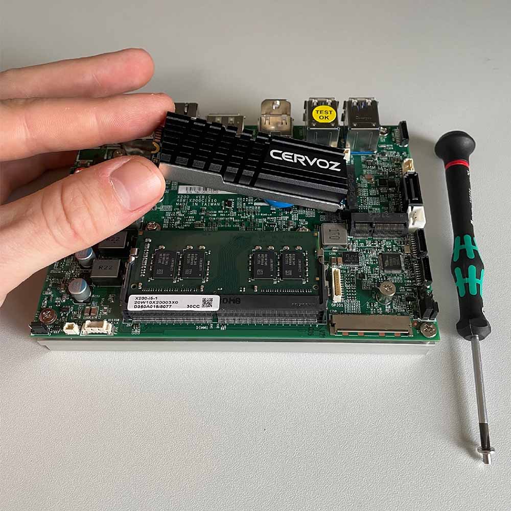
When the M.2 module and motherboard have been confirmed to have the same compatibility, you can install very simply by inserting the card at a 30˚degree angle, press the card down parallel with the motherboard, and screw the semicircle gap at the end of the card to secure the module on the motherboard.
M.2 Keys and Form Factors Explained
M.2 sockets have key characteristics which defines which M.2 modules are supported. When the module and motherboard have the same compatibility, you can insert the card at a 30˚degree angle, press the card down parallel with the motherboard, and screw the semicircle gap at the end of the card to secure the module on the motherboard. First, we must check your M.2 module is compatible with the designated host with the correct form factor and keying.
M.2 Form Factors (M.2 Sizes)

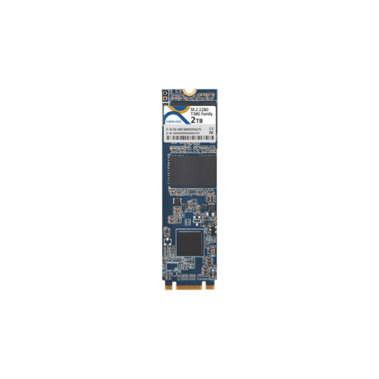
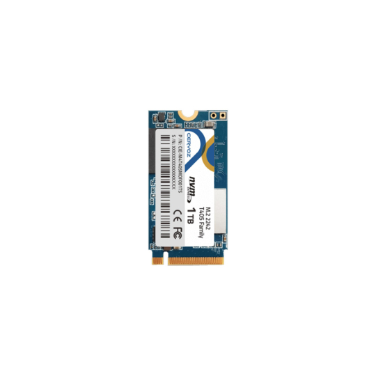
The M.2 form factor attribute is relatively straight forward and is simply a measurement of its width and length. The width and length of the associated M.2 module or installation capability for the M.2 slot onboard the motherboard is associated with a 4-digit code which contains this information. The available widths across the range of M.2 modules are 12,16,22, and 30mm. These different width cards also com in different lengths, supporting 16, 26, 30, 38, 42, 60, 80 and 110mm lengths. Some host motherboards will support M.2 devices with varying lengths by provisioning mounting points in multiple locations on their board, giving the user much greater flexibility for available cards or greater storage capacities. An example M.2 code could be “2280”, meaning the M.2 module is 22 mm wide and 80 mm long, a very common form factor for M-Key SSDs.
M.2 modules have varying levels of thickness with single-sided and double-sided modules also supporting on-board fans or heatsinks for additional cooling. The standard thickness of the M.2 PCB (Plastic Circuit Board) is 0.8 mm with a tolerance of ± 10%. Both single-sided and double-sided M.2 modules also have a tolerance which cannot exceed 1.5mm either side. Understandably, a single-sided M.2 module allows for space-constrained applications with small form factor PCs. Alternatively, using double-sided M.2 modules enable more chips to fit onboard the M.2 PCB. This can increase the overall storage capacity or advance onboard technology whilst maintaining a compact footprint. In some use cases, such as M.2 video capture cards, an onboard heatsink is required for cooling the chipsets when running demanding applications or processing large volumes of data.
M.2 Keys: Key A, Key B, Key E, Key M, Key A+E, Key B+M
M.2 slots hosted on the industrial motherboard have an arrangement of pins available by the M.2 socket. This defines which host interface, or which M.2 modules, can be installed onto the motherboard to guarantee compatibility. A total of up to 67 pins is supported via the M.2 socket and there is a standardized guide to keying which is used to prevent incompatible cards being inserted onto host systems. Although there is a total of 12 key IDs available as per the M.2 standard, most are not yet in use for either commercial or industrial application use cases. The table in the section below lists the common A, B, E, & M-key interfaces and associated modules which utilize these types of interfaces. For example, an M.2 M-Key PCIe SSD can utilize either PCIe x4 or PCIe x2 interface to communicate with the host.

This covers which host interfaces can be used via various key configurations. However, more attention to detail is required if you want to maximise the capability of your intended M.2 module when installing into the host M.2 socket. Sometimes manufacturers will list the host sockets as either A+E Key or B+M Key which as expected means the module will fit, however, a particular key may be required to utilize more bandwidth. For instance, SSDs utilising the SATA bus can use both B+M keys, but the M-Key slot won’t be utilising its max sequential read/write capabilities offered by the PCIe x4 bus interface if a SATA SSD was installed.
A-Key, B-Key, E-Key & M-Key M.2 Connectors and Interfaces
B-Key Connectors: Has a six-pin gap at the left side of the card, and the right side is the host controller.
E Key Connectors: Has a twelve-pin gap at the left side of the card, and the right side is the host controller.
M Key Connectors: Has a five-pin gap at the right side of the card, and the left side is the host controller.
M.2 Key A
M.2 Key A is characterized by having a notch on the bottom side of the connector and six pins on the edge connector side. It is primarily used for wireless communication modules, such as Wi-Fi and Bluetooth cards.
M.2 A-Key Pin Location: 8-15
M.2 A-Key Interfaces: PCIe x1, USB2.0, I2C, DP x4
M.2 A-Key Modules: Wireless: Wi-Fi, BT, NFC
M.2 Key B
M.2 Key B is characterized by having a notch on the bottom side of the connector and five pins on the edge connector side. It is commonly used for a variety of components, including SSDs and cellular 4G LTE or 5G networking cards.
M.2 B-Key Pin Location: 12-19
M.2 B-Key Interfaces: PCIe x2, USB3.0, SATA, HSIC, SSIC, Audio, UIM, I2C
M.2 B-Key Modules: Cellular & GNSS or SSD
M.2 Key E
M.2 Key E is characterized by having a notch on the bottom side of the connector and two pins on the edge connector side. It is primarily used for wireless communication modules, such as Wi-Fi and Bluetooth cards.
M.2 E-Key Pin Location: 24-31
M.2 E-Key Interfaces: PCIe x1, USB2.0, I2C, SDIO, UART, PCM
M.2 E-Key Modules: Wireless: Wi-Fi, BT, NFC, & GNSS
M.2 Key M
M.2 Key M is characterized by having a notch on the bottom side of the connector and five pins on the edge connector side. It is primarily used for high-performance storage devices, such as NVMe (Non-Volatile Memory Express) SSDs.
M.2 M-Key Pin Location: 59-66
M.2 M-Key Interfaces: PCIe x4, SATA
M.2 M-Key Modules: SSDs, Video Capture Cards, & AI Accelerators
Types Of M.2 Interface and Data Transfer Protocol
Much like mPCIe, M.2 expansion also carries various signal interfaces and new storage protocols which defines the compatibility of devices onboard the host motherboard. Manufacturers will list the supported M.2 signal interfaces and protocols on their datasheets to help you understand whether or not they would be able to communicate accordingly.
M.2 Signal Interfaces: PCI Express, SATA & USB
The M.2 interface was developed by Intel to not only be powerful but also offer a high degree of flexibility for a wide array of applications. Supporting PCI Express (PCIe 3.0 and PCIe 4.0), Serial ATA (SATA 3.0), and SuperSpeed USB, M.2 expansion supports multiple signal interfaces. This variety of bus interfaces enable advancements in embedded and industrial applications across a plethora of vertical markets. The next generation form factor is a highly flexible and versatile for high-speed storage applications, AIoT with performance accelerators and video capture cards, IIoT with a multitude of wireless and cellular connectivity, and general automation with I/O expansion modules.
M.2 Storage Protocols: AHCI & NVMe
M.2 modules are available with different storage protocols, including SATA (AHCI), PCI Express (PCIe), and NVMe. SATA-based M.2 modules are backward compatible with SATA 3 Gbit/s and SATA 6 Gbit/s ports, while PCIe-based M.2 modules are only compatible with PCIe slots. SATA is now a legacy standard which uses AHCI (Advanced Host Controller Interface) as the storage protocol which has been around since HDD (hard disk drive) storage devices with spinning metal discs. NVMe is a new storage protocol that is specifically designed for SSDs that use the PCIe bus. This new standard of Non-Volatile Memory Express takes full advantage of flash chip storage, known as NAND chips. NVMe offers significantly higher performance than SATA-based SSDs, but it is not compatible with SATA ports or slots.

M.2 SATA SSDs
M.2 PCIe SSDs
M.2 NVMe SSDs
M.2 SATA vs NVMe SSD Storage
SATA interface SSDs have a bottleneck speed of 6Gb/s, making the transfer rate compared to PCIe very slow, making the main difference between M.2 SATA SSDs and M.2 PCIe NVMe SSDs the speed. PCIe 4.0 lane support guarantees a 16Gb/s transfer rate for each PCIe lane. When comparing M.2 key types, you will see the modules are capable of utilizing x2 or up to x4 PCIe lanes for high-performance, low latency SSDs. If you’re looking for extremely fast NVMe SSDs, you want to choose an M.2 M-Key SSD as they support up to four lanes of PCIe signals which fully optimizes your SSD speeds.
M.2 SATA SSD (AHCI Protocol): Read and write speeds of 500MB/s.
M.2 PCIe SSD (AHCI Protocol): Read and write speeds of 2Gb/s and 1.5Gb/s.
M.2 PCIe NVMe SSD: Read and write speeds of 3.5Gb/s and 2.45GB/s.
As you can see above, M.2 SSDs can transfer data 50% to around 650% faster than the SATA SSDs. If you compare the sequential read and sequential write cycles for both PCIe and SATA SSDs, M.2 PCIe NVMe SSDs theoretically support up to 3,500Mb/s sequential read and 2,450MB/s sequential write speeds whereas SATA 6Gb/s SSDs have a 500MBps bottleneck for both reading and writing. This is why NVMe SSDs are renowned for blazingly fasts read and write capabilities.
With plenty of M.2 SSDs now available in the embedded and industrial marketplace with different sizes and specifications the choice for form factor and storage capacity is key. As a general de facto, larger storage capacity M.2 SSDs require more NAND flash storage chips which ultimately leads to a bigger M.2 form factor being required. Mini PCs and small form factor SBCs will typically sacrifice speed or size in requirements for onboard density.
Looking To Install M.2 Modules Onboard Industrial Computing?
Tell us about your application and a member of our team will get right back to you.