
 US
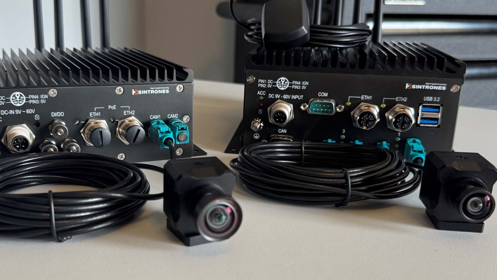
GMSL3 vs GMSL2: Understanding GMSL Technology for Industrial Edge AI
GMSL3 doubles the GMSL2 link to 12 Gbps for higher-resolution cameras. Here is what changes between the generations, how much bandwidth each camera needs, how far the cables run and how GMSL reaches NVIDIA Jetson from Orin to Thor.
GMSL3 is the third generation of the Gigabit Multimedia Serial Link, a serialiser–deserialiser (SerDes) interface that carries up to 12 Gbps of uncompressed camera or sensor data, plus power and control signals, over a single coaxial or shielded twisted pair cable. It doubles the 6 Gbps of GMSL2, which is the generation most industrial cameras and Jetson computers use today, and GMSL3 parts can run GMSL2 links so the two can share a system.
GMSL was first created by Maxim Integrated in California. Analog Devices acquired Maxim in 2021 and has continued the technology since. It was designed for cars, where cameras, radar and displays sit meters from the processor, but GMSL is now common in automated guided vehicles (AGVs), collaborative robots (cobots), autonomous mobile robots (AMRs), agricultural and off-highway machines, and inspection systems.
High-speed sensor links matter because edge AI computers such as NVIDIA Jetson systems process camera streams in real time, and the model can only be as good as the frames that reach it. This guide explains what changes from GMSL2 to GMSL3, how much bandwidth each carries, how far the cables run, how GMSL reaches a Jetson from Orin to Thor, and what makes the integration hard. For the camera side, including the Stereolabs ZED X, see our guide to the GMSL camera interface.
“GMSL is a high-performance, high-speed interface recognized for its high data rates, low latency and reliability, making it especially valuable in automotive and robotics applications. While features such as Power-over-Coax bring clear benefits, complex system and software integration remain a significant challenge. We work closely with both industrial edge AI computer and camera manufacturers to simplify this integration and help customers accelerate their time-to-market.” Andrew Whitehouse, CEO at Things Embedded
Key takeaways
- 01GMSL3 doubles the link rate
- GMSL3 carries up to 12 Gbps forward, against 6 Gbps for GMSL2 and roughly 3 Gbps for the fastest GMSL1 parts.
- 02GMSL2 still covers most cameras
- A single 8MP camera at 30 fps fits comfortably in GMSL2; GMSL3 earns its place at 60 fps, above 8MP or when two sensors share a link.
- 03One cable for video, power and control
- Power over Coax, I²C or UART control and frame triggers all share the same coax or shielded twisted pair.
- 04The cable budget decides the reach
- Reach of around 15 m is typical, but GMSL3’s higher frequencies make cable and connector loss tighter than on GMSL2.
- 05Integration is the hard part
- Matched serializer and deserialiser parts, I²C addressing, virtual channels and the device tree decide whether frames arrive.
GMSL1, GMSL2 and GMSL3 compared
The table compares the three generations. Figures come from Analog Devices’ published device and channel information and are typical; individual parts vary, so check the data sheet of the exact serializer and deserialiser.
| Feature | GMSL1 | GMSL2 | GMSL3 |
|---|---|---|---|
| Forward (video) rate | Roughly 1.5–3.12 Gbps, depending on the part | 3 or 6 Gbps | Up to 12 Gbps |
| Reverse (control) channel | Low-rate control channel | 187.5 Mbps | 187.5 Mbps |
| Video interface to the sensor | Parallel or early CSI-2 | MIPI CSI-2, parallel, HDMI or DisplayPort, depending on the part | MIPI CSI-2 (C-PHY and D-PHY on newer parts) |
| Cable | Coax or shielded twisted pair | Coax or shielded twisted pair | Coax or shielded twisted pair |
| Typical reach | Up to about 15 m | Up to about 15 m | Up to about 15 m, with a tighter loss budget |
| Power over the same cable | Yes, with PoC circuits | Yes, Power over Coax | Yes, Power over Coax |
| Example serialisers | MAX9271, MAX96705 | MAX9295A, MAX96717 | MAX96793 |
| Example deserialisers | MAX9272, MAX9286 | MAX9296A, MAX96712, MAX96724 | MAX96792A |
| Backward compatibility | n/a | Some deserialisers also accept GMSL1 cameras | Runs GMSL2 modes, so GMSL2 cameras can connect |
| Typical use today | Older automotive and legacy camera designs | Most industrial and robotics GMSL cameras | High-resolution and high-frame-rate cameras, newer automotive sensors |
In practice the step from GMSL1 to GMSL2 was the big change for industrial users: a protocol built on packets rather than a fixed video bus, a much faster reverse channel and support for several video streams on one link. GMSL3 keeps that architecture and doubles the rate. That is why the device tree and driver approach used for GMSL2 carries across, and why a GMSL3 system can usually reuse GMSL2 cameras where they are fast enough.
What is GMSL3?
GMSL3 is a point-to-point serial link between a sensor and a processor. A serializer beside the image sensor takes the sensor’s MIPI CSI-2 output, packs it into a high-speed serial stream and drives it down the cable. A deserialiser on the computer side recovers the stream and presents it to the processor as MIPI CSI-2 again, so the processor sees what looks like a local camera even when the sensor is several meters away.
Analog Devices positions GMSL3 for the cameras and displays that GMSL2 cannot carry at full rate: sensors of 8MP and above at high frame rates, cameras with several exposures for high dynamic range, and links that aggregate more than one sensor. Its parts are designed to support ISO 26262 functional safety, with many devices rated to ASIL-B, which matters for driver assistance and is increasingly asked for in mobile robots and off-highway machines that share their safety case.
The reverse channel stays at 187.5 Mbps. That is ample for what flows back towards the camera: I²C or UART register writes, frame-sync triggers, GPIO and occasional firmware updates.
What is the bandwidth of GMSL3?
GMSL3 runs at up to 12 Gbps in the forward direction, twice the 6 Gbps of GMSL2. The useful payload is a little lower, because the link carries packet headers, error checking and blanking as well as pixels, so it is sensible to plan on 80–90 % of the line rate for video.
The easiest way to see where GMSL3 is needed is to work out what a camera produces. Uncompressed video needs width × height × bits per pixel × frames per second. The table uses RAW12, a common output for automotive and machine vision sensors, and YUV 4:2:2 at 16 bits per pixel for cameras that process the image on board.
| Camera stream | Raw data rate | GMSL2 at 6 Gbps | GMSL3 at 12 Gbps |
|---|---|---|---|
| 1920 × 1080, RAW12, 30 fps | About 0.75 Gbps | Fits easily | Fits easily |
| 1920 × 1200, YUV 4:2:2, 60 fps | About 2.2 Gbps | Fits | Fits |
| Stereo pair, 2 × 1920 × 1200, YUV 4:2:2, 60 fps | About 4.4 Gbps | Fits, with little spare | Fits with room for a second camera |
| 3840 × 2160 (8.3MP), RAW12, 30 fps | About 3.0 Gbps | Fits | Fits |
| 4000 × 3000 (12MP), RAW12, 30 fps | About 4.3 Gbps | Tight once overhead is added | Fits |
| 3840 × 2160, RAW12, 60 fps | About 6.0 Gbps | Does not fit | Fits |
| Two 8.3MP cameras aggregated on one link, 30 fps | About 6.0 Gbps | Does not fit | Fits |
Worked example. An inspection gantry needs 4K images at 60 fps to catch defects on a moving web. Each camera produces about 6 Gbps before overhead, more than a GMSL2 link carries, so the choice is GMSL3, a lower frame rate, a smaller region of interest or compression on the camera. For a mobile robot with 2.3MP global shutter stereo cameras at 60 fps, GMSL2 has headroom and remains the practical choice. Our explainer on global shutter vs rolling shutter covers why those robot cameras favor lower-resolution global shutter sensors.
Bandwidth at the processor matters too. Each deserialiser output feeds MIPI CSI-2 lanes on the host, and four GMSL3 links into one deserialiser can deliver more data than one CSI-2 port accepts. Check the host’s MIPI CSI-2 lane count and lane rate before planning several high-rate cameras on one board.
How a GMSL link works
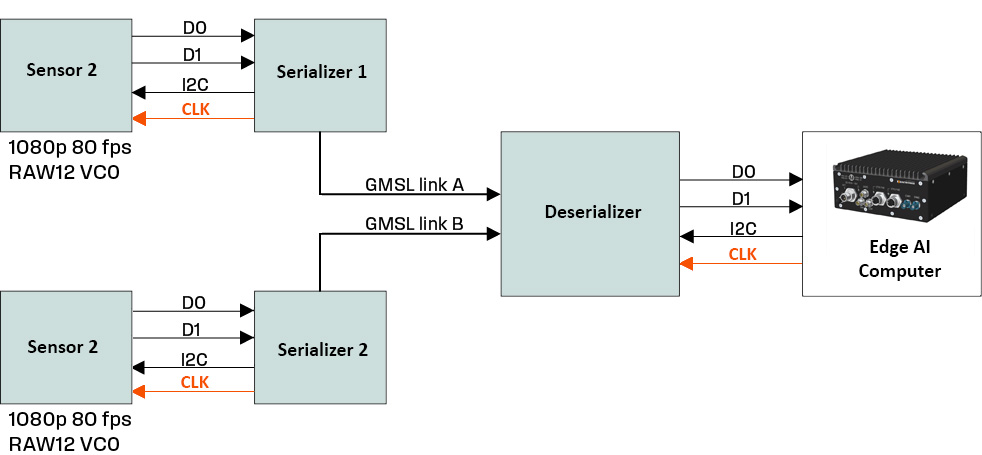
GMSL carries video uncompressed, which is what keeps latency low and image quality unchanged. A serializer (SerDes) takes the data from the sensor and converts it into a high-speed serial stream, which is sent in packets over the cable. At the receiving end a deserialiser reconstructs the packets so the embedded computer can process the data. Once received, the video can be used in applications such as driver assistance, precision agriculture, environmental monitoring and autonomous navigation.
GMSL2 and GMSL3 are full duplex. Alongside the video, the same link carries control commands, synchronization signals, touch and haptic data on display links, software updates and status messages, using tunnelled I²C, UART and SPI. Power over Coax (PoC) adds the camera’s supply, so one coaxial cable does the work of three or four separate wires. That reduces system cost and improves reliability, because cables and connectors are common points of failure.
| What travels on the link | Direction | Notes |
|---|---|---|
| Video from the sensor (MIPI CSI-2 packets) | Forward | Uncompressed; several virtual channels can share one link |
| Embedded data and sensor metadata | Forward | Exposure, temperature and frame counters from the sensor |
| I²C or UART register access | Reverse and forward | Lets the host configure the sensor and serializer as if they were local |
| Frame-sync trigger and GPIO | Reverse | Hardware triggers keep several cameras capturing in step |
| Camera power | Forward, as DC on the cable | Power over Coax; the ZED Link cards supply 12 V |
| Error checking and link status | Both | CRC and retransmission on control traffic, link-lock indication |
Because the link carries an exact copy of the sensor’s CSI-2 output, the host does not decode anything. That is the main difference from GigE Vision cameras, which packetise frames for an Ethernet network and need the host to reassemble them.
Is GMSL3 backward compatible with GMSL2?
Yes, in the sense that matters for most projects. GMSL3 serialisers and deserialisers can run GMSL2 link modes at 6 or 3 Gbps, so a GMSL3 deserialiser board can take GMSL2 cameras, and a GMSL3 camera can run in a GMSL2 mode on a GMSL2 board at the lower rate. Compatibility is set per part and per link, so it is checked against the exact devices rather than assumed.
| Camera (serialiser) | Computer (deserialiser) | Link rate | Works? |
|---|---|---|---|
| GMSL2 | GMSL2 | 3 or 6 Gbps | Yes, the common case today |
| GMSL2 | GMSL3 | 3 or 6 Gbps | Yes, with the deserialiser port set to GMSL2 mode |
| GMSL3 | GMSL3 | Up to 12 Gbps | Yes |
| GMSL3 | GMSL2 | Up to 6 Gbps | Only if the camera supports a GMSL2 mode and its stream fits |
| GMSL1 | GMSL2 or GMSL3 | GMSL1 rates | Only on deserialisers with GMSL1 support, such as some quad parts |
Two rules hold across every generation. The serializer and deserialiser must be compatible parts, normally from the same family and configured for the same mode, and the deserialiser’s CSI-2 output must suit the host processor. A link that never locks is very often a mode mismatch rather than a fault.
How far can GMSL3 run over coax?
Typically up to about 15 m, the same headline reach as GMSL2, but the margin is smaller. A GMSL link is limited by how much signal the cable, connectors and any in-line joints lose at the link’s frequency, not by a fixed length. Analog Devices publishes channel specifications for GMSL2 and GMSL3 (application note AN-2585 and the GMSL3 channel specification user guide) that set limits for insertion loss, return loss and crosstalk across frequency. If the whole channel stays inside those limits, the link is within specification at whatever length that allows.
GMSL3 signals at higher frequencies than GMSL2, and coax loses more per meter as frequency rises. In practice that means a cable that just passes at 6 Gbps over 15 m may need a lower-loss type, fewer in-line connectors or a shorter run at 12 Gbps. Shielded twisted pair is also supported and suits some harnesses, usually over shorter distances than good coax.
| Factor | Effect on reach | What to do |
|---|---|---|
| Cable type and gauge | Thinner, cheaper coax loses more per meter | Use the cable the camera maker qualifies, or one proven against the channel spec |
| Number of in-line connectors | Each joint adds loss and reflections | Avoid bulkhead and splice joints where possible |
| Connector family | Older connectors were designed for lower frequencies | FAKRA for most GMSL2; higher-bandwidth automotive connectors for many GMSL3 designs |
| Temperature | Cable loss rises when hot | Check the loss at the maximum ambient, not at room temperature |
| Power over Coax filtering | Poor PoC filters distort the signal | Use the PoC circuit from the reference design |
| Bend radius and flexing | Tight bends and repeated flexing change the impedance | Use drag-chain rated cable on moving axes |
Most GMSL2 cameras in our range use Z-coded FAKRA connectors, which lock positively and are keyed so a camera cannot be plugged into the wrong port. Multi-port boards often use quad or mini FAKRA housings to save panel space. Many GMSL3 designs move to newer automotive connectors with more bandwidth, so check that the camera, cable and computer connectors match before ordering. For sealed outdoor systems, the connector also has to keep the computer’s IP rating; our IP rating chart explains the levels.
GMSL on NVIDIA Jetson, from Orin to Thor
Jetson modules have no GMSL input of their own. They take MIPI CSI-2, so GMSL reaches a Jetson through a deserialiser on the carrier board or on a capture card that connects to the carrier’s camera connector. Jetson AGX Orin has 16 CSI-2 lanes and the most room for camera streams; Jetson Orin NX and Orin Nano have 8. Virtual channels let several cameras share each CSI-2 port, which is how eight GMSL2 cameras reach an AGX Orin.
With Jetson Thor, NVIDIA adds a second camera path. Thor keeps MIPI CSI-2 inputs, and it also takes sensor data over Ethernet through the NVIDIA Holoscan Sensor Bridge, which packetises camera data and delivers it over high-speed Ethernet into GPU memory. That lets camera links run further and lets one Thor system collect many sensors. Holoscan Sensor Bridges with GMSL2 inputs bridge existing GMSL cameras onto that path.
| Jetson module | Camera interface | GMSL inputs in systems from our range | Example |
|---|---|---|---|
| Jetson Orin Nano | 8 CSI-2 lanes | 2–6 × GMSL2 | ZED Box Mini, DFI X6-ORN-GMSL |
| Jetson Orin NX | 8 CSI-2 lanes | 2–8 × GMSL2 | Neousys NRU-51V+, AVerMedia D135 GMSL build |
| Jetson AGX Orin | 16 CSI-2 lanes | 8 × GMSL2 (some boards GMSL1 or GMSL2) | Neousys NRU-230V-AWP, Vecow RAC-1000 |
| Jetson Thor (T4000, T5000) | CSI-2 plus Holoscan Sensor Bridge over Ethernet | Optional 8 × GMSL2 | Forecr DSBOX‑THRMAX, Advantech MIC-742-AT |
Does Jetson Thor support GMSL3? The Thor computers in our range currently offer eight GMSL2 inputs as a factory option, and GMSL2 covers the robot and vehicle cameras most projects use. GMSL3 deserialiser boards for Thor are appearing from carrier and camera makers as GMSL3 cameras arrive. Because GMSL3 deserialisers also run GMSL2 links, a Thor design that needs GMSL3 later can usually keep its GMSL2 cameras. If GMSL3 is on your roadmap, tell us the camera and we will check the deserialiser, driver and JetPack release before you commit.
Software support follows the deserialiser, not the GMSL generation. Each board needs a kernel driver for its deserialiser and a device tree that matches its wiring, built for the exact JetPack release. Our guide to choosing a Jetson carrier board covers the other connectors and I/O to check at the same time.
Why GMSL integration is harder than USB or Ethernet
Despite its strengths, GMSL is more complex to integrate than USB or Ethernet. Developers often face hurdles with virtual channels, addressing and timing, which require careful attention to both hardware configuration and software. The serializer and deserialiser must be matched, and the deserialiser must be compatible with the host processor and its MIPI CSI-2 output format. These are the four areas where projects most often stall.
| Challenge | What goes wrong | How it is solved |
|---|---|---|
| I²C addressing and proxy addresses | Identical cameras share the same physical I²C address, so commands reach the wrong camera or none | The deserialiser assigns unique proxy addresses at runtime, so each sensor and serializer is addressed unambiguously |
| Virtual channels | Streams from several cameras arrive on one CSI-2 port mislabelled or dropped | Each stream gets a virtual channel ID, configured identically on the sensor, serializer, deserialiser and receiver |
| Device tree configuration | The camera appears present but capture times out | The device tree must describe CSI lanes, bandwidth settings, power supplies and component mapping exactly as the board is wired |
| Synchronization and timing | Frames drift apart, flicker during scene changes or lose quality | Hardware frame-sync over the reverse channel, matched lane settings and consistent clocking |
Synchronization matters most in multi-camera systems. When several sensors share one CSI port, mismatched lane configurations or asynchronous modes can cause data loss or misread signals, which shows up as image flicker during scene transitions or poor sensor calibration. Some systems also align cameras with LiDAR and GNSS using a pulse-per-second input or Precision Time Protocol, and our paper on IEEE 1588 for machine vision covers that side.
This is integration work rather than product selection. We configure, image and test every GMSL system with the customer’s cameras and cable lengths connected, confirm that each camera enumerates and that sync holds across the array, and ship it with the drivers in the operating system image. Our paper on PoE power budgeting for multi-camera edge AI covers the IP camera alternative, where power rather than bandwidth is often the limit.
GMSL in industrial and outdoor systems
GMSL comes from the car, so the silicon is built for heat, vibration and electrical noise. The computer around it has to match. These are the industrial checks we make alongside the camera link itself.
| Requirement | Why it matters for GMSL systems | Typical specification |
|---|---|---|
| Operating temperature | Cameras and computers on vehicles and outdoor machines see sun load and cold starts | Computers from −25 to 70 °C or wider; ZED X cameras −20 to 60 °C |
| Wide-range DC input | Vehicles run from 12, 24 or 48 V with spikes and dips | 9–50 V DC with ignition control on many vehicle computers |
| Sealing | Washdown, rain and dust on outdoor robots and machines | IP66 or IP67 computers with sealed FAKRA connectors |
| Shock and vibration | Connectors and boards must survive years of vibration | Tested to MIL-STD-810H or IEC 60068 by the manufacturer |
| Functional safety | Driver assistance and some machine safety cases need certified links | GMSL parts designed for ISO 26262, many rated ASIL-B |
| Lifecycle | Automotive SerDes parts and Jetson modules have long availability | Plan module and camera availability for repeat builds |
For vehicles, see our in-vehicle computers; for sealed outdoor systems, our rugged Jetson computers are the usual starting point. Our Jetson thermal design guide explains how sealed GMSL computers hold full AI performance in the heat.
GMSL compared with other camera links
GMSL is one of several ways to get a camera onto an edge AI computer. Each suits a different distance, bandwidth and cost. Our GMSL camera interface guide, linked above, compares them in more depth with Stereolabs ZED X cameras as the worked example.
| Interface | Typical reach | Bandwidth per camera | Power on the cable | Best for |
|---|---|---|---|---|
| GMSL2 | Up to about 15 m coax | Up to 6 Gbps | Yes, PoC | Robots and vehicles with several synchronized cameras |
| GMSL3 | Up to about 15 m, tighter budget | Up to 12 Gbps | Yes, PoC | High-resolution, high-frame-rate cameras |
| MIPI CSI-2 direct | Tens of centimeters | Several Gbps | No | Cameras on the same board or enclosure |
| GigE Vision | Up to 100 m copper | 1–10 Gbps | Yes, with PoE | Fixed inspection cells and long runs |
| USB3 Vision | Up to about 5 m passive | Up to 5 Gbps | Yes, bus power | Benches, labs and short runs |
GMSL hardware in our range
From cameras to capture cards and the Jetson computers that host them, each range covers part of the GMSL signal path.

GMSL cameras
Stereolabs ZED X stereo and ZED X One mono cameras with GMSL2 links and hardware sync.
View range
Frame grabbers
GMSL2, Ethernet and USB capture cards for Jetson and x86 computers.
View range
Jetson AGX Orin carrier boards
AGX Orin carrier boards, several with GMSL2 camera inputs, for custom builds.
View range
Jetson Thor carrier boards
Thor carrier boards with 25GbE and camera options for sensor-heavy robots.
View range
Holoscan sensor bridges
Bridges that carry GMSL2 camera feeds to a Holoscan pipeline over fiber.
View range
Stereo cameras
Depth cameras for robots and vehicles, over GMSL2 or USB.
View rangeGMSL systems from our range
These systems cover the main GMSL setups, from a single camera on an Orin Nano to eight cameras on Jetson Thor. All are GMSL2 today. We fit the deserialiser drivers, configure the device tree for your cameras, image the operating system and test capture and sync with your cable lengths before the system ships.
| System | Jetson module | GMSL inputs | Notes from the product data |
|---|---|---|---|
| Stereolabs ZED Box Mini | Orin Nano or Orin NX | 2 × GMSL2 on FAKRA-Z | Frame-sync trigger in and out; built for ZED X cameras |
| DFI X6-ORN-GMSL | Orin Nano or Orin NX | 2 × GMSL2 on FAKRA Z-code | One 4K camera at 30 fps or two at 1080p 60 fps; fanless |
| Neousys NRU-51V+ | Orin NX or Orin Nano | 4 × GMSL2 | Cameras synchronized to within microseconds; GPS PPS input for LiDAR alignment |
| Neousys NRU-230V-AWP | AGX Orin | 8 × GMSL2 on waterproof FAKRA Z | IP66 outdoor computer, up to 275 TOPS |
| Vecow RAC-1000 | AGX Orin | 8 × GMSL1 or GMSL2 on FAKRA-Z | IP67, isolated CAN FD, M12 I/O |
| Forecr DSBOX‑THRMAX | Jetson T4000 or T5000 | Optional 8 × GMSL2 on quad FAKRA | 4 × 25GbE QSFP28 for sensor bridges |
| Neousys PCIe-NPL54 | None (x86 host) | 4 × GMSL2 on FAKRA Z | PCIe Gen2 x4 card for Intel and AMD computers; GPS PPS sync |
GMSL computers and capture cards
Seven starting points, from a two-camera ZED Box Mini to an eight-camera Jetson Thor system and a GMSL2 card for x86 computers.
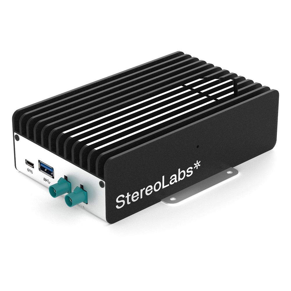
NVIDIA Jetson Orin NX 16GB Embedded Box PC with 2x GMSL2 Cameras, 100 TOPS and -20 °C Operation
- AI
- 100 TOPS
- SOM
- NVIDIA Jetson Orin NX 16 GB
- Cameras
- 2× GMSL
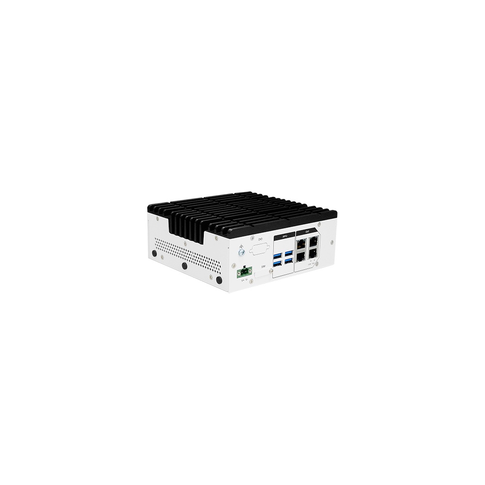
NVIDIA Jetson Orin NX 16GB Fanless Machine Vision Computer with GMSL2 Cameras and 4x GbE
- AI
- 100 TOPS
- SOM
- NVIDIA Jetson Orin NX 16 GB
- Cameras
- 2× GMSL
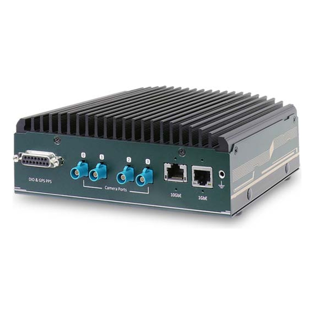
NVIDIA Jetson Orin NX or Orin Nano Rugged Embedded Computer with 4x GMSL2 Cameras and 10GbE
- AI
- 20–100 TOPS
- SOM
- NVIDIA Jetson Orin NX 16 GB
- Cameras
- 4× GMSL
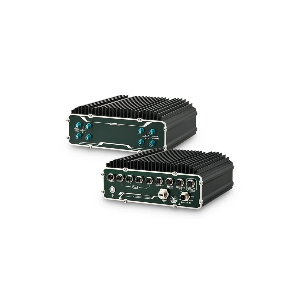
NVIDIA Jetson AGX Orin 64GB IP66 Outdoor Computer with 8x GMSL2 and 10GbE
- AI
- 275 TOPS
- SOM
- NVIDIA Jetson AGX Orin 64 GB
- Cameras
- 8× GMSL
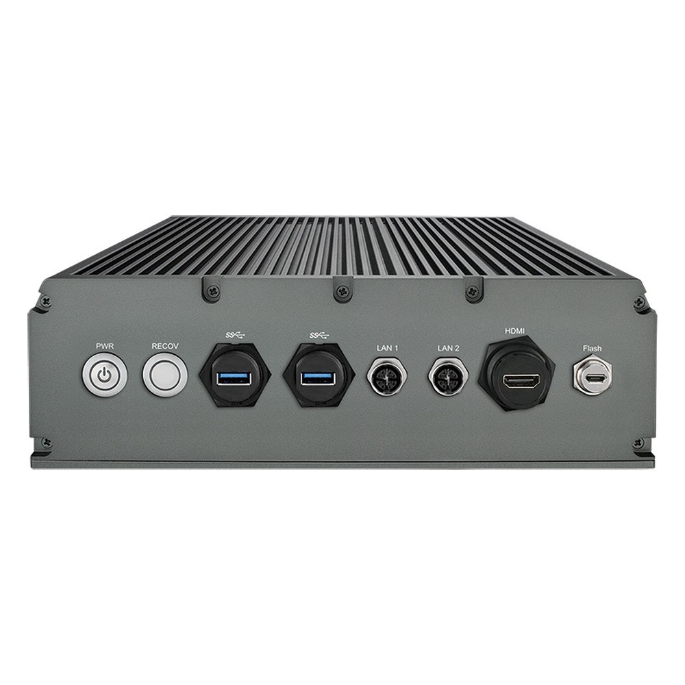
NVIDIA Jetson AGX Orin 64GB IP67 Waterproof Computer with 275 TOPS, 8 GMSL Cameras and 9-50V DC
- AI
- 275 TOPS
- SOM
- NVIDIA Jetson AGX Orin 64 GB
- Cameras
- 8× GMSL
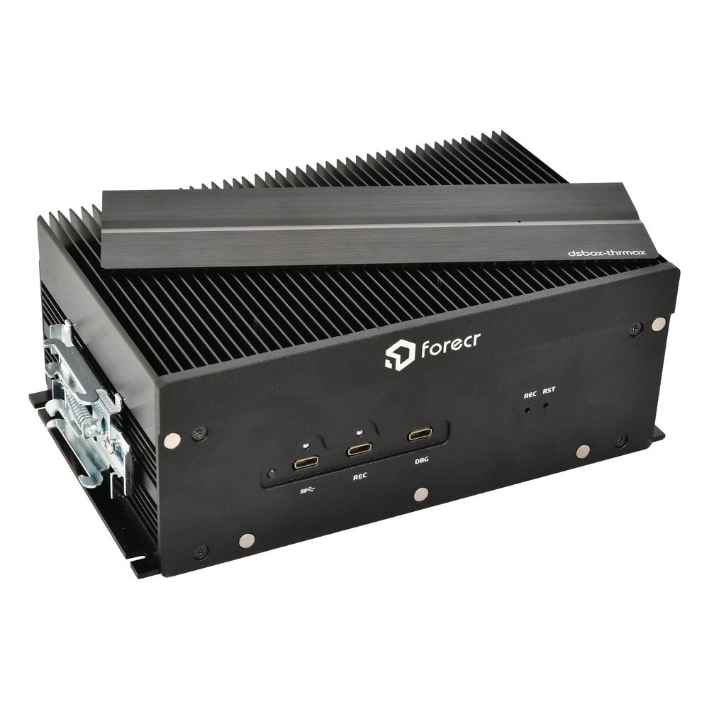
NVIDIA Jetson AGX Thor T5000 Industrial Box PC with 4x 25GbE QSFP28, Dual HDMI and Optional 8x GMSL2
- AI
- 2,070 TOPS
- SOM
- NVIDIA Jetson T5000
- Ethernet
- 4× 25GbE, 1× GbE
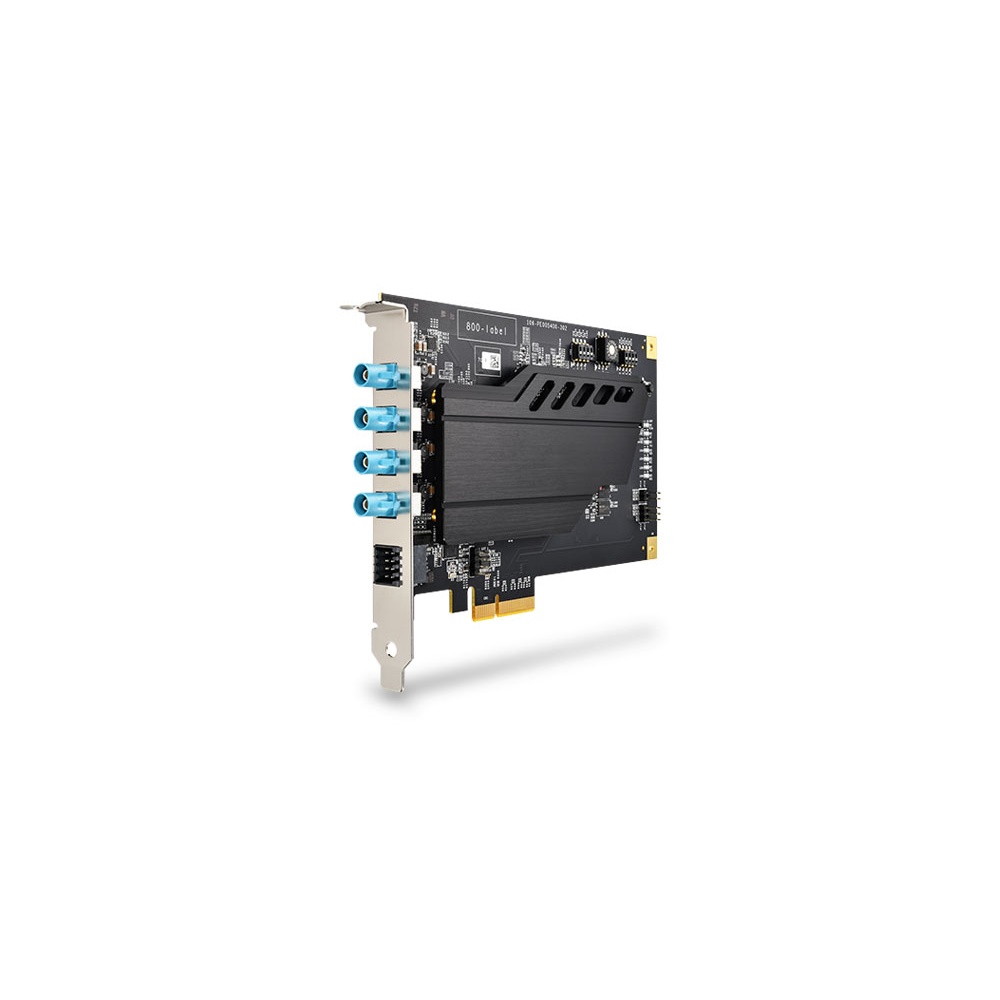
Fanless Frame Grabber Card with 4x GMSL2 Automotive Cameras
- Inputs
- 4× GMSL2
- Max input
- 4K30 (3840×2160)
- Interface
- PCIe
Planning a GMSL2 or GMSL3 camera system
Seven checks that settle the link before cameras and computers are ordered.
-
01
Data rate per camera
Work out width × height × bits per pixel × frame rate, then add overhead; above about 5 Gbps, plan for GMSL3.
-
02
Cameras per link
Decide whether any link aggregates two sensors, which can double the rate it needs.
-
03
Deserialiser and mode
Match serializer and deserialiser parts and set every port to the same GMSL mode and rate.
-
04
Host CSI-2 capacity
Check the Jetson module’s CSI-2 lanes and virtual channels can take every stream at once.
-
05
Cable and connectors
Choose cable and connectors that meet the channel loss budget at the maximum temperature.
-
06
Sync and timing
Plan hardware frame-sync and any PPS or PTP alignment with LiDAR, GNSS or other computers.
-
07
Software release
Confirm the deserialiser driver and device tree exist for your JetPack release before ordering.
GMSL3: common questions
Quick answers
What is GMSL3?
The third generation of the Gigabit Multimedia Serial Link. It carries up to 12 Gbps of uncompressed camera data, plus power and control, over one coaxial or shielded twisted pair cable between a serializer at the camera and a deserialiser at the computer.
What is the bandwidth of GMSL3?
Up to 12 Gbps forward. The reverse control channel runs at 187.5 Mbps. Plan on 80–90 % of the forward rate for video once protocol overhead is included.
Is GMSL3 backward compatible with GMSL2?
Yes, at GMSL2 rates. GMSL3 parts can run GMSL2 links at 3 or 6 Gbps, so GMSL2 cameras work on GMSL3 deserialisers configured for GMSL2 mode. Check the exact parts.
What is the difference between GMSL2 and GMSL3?
Mainly the rate. GMSL3 doubles the forward link from 6 to 12 Gbps for higher-resolution and higher-frame-rate cameras, with a tighter cable loss budget. The architecture, reverse channel and software model are similar.
How far can GMSL3 run over coax?
Typically up to about 15 m. The real limit is the channel loss budget, so cable type, connectors and temperature decide the reach. At 12 Gbps the margin is smaller than at 6 Gbps.
Does Jetson Thor support GMSL3?
Through the carrier or a camera board, not natively. Jetson takes MIPI CSI-2 and, on Thor, Holoscan Sensor Bridge data over Ethernet. Thor systems in our range offer eight GMSL2 inputs; GMSL3 boards depend on the carrier maker.
Does GMSL carry power?
Yes. Power over Coax puts the camera’s DC supply on the same cable as video and control, so each camera needs only one cable.
GMSL and camera interface FAQs
-
What Is GMSL2?
GMSL2 (Gigabit Multimedia Serial Link 2) is a high-speed serial link that carries uncompressed camera video, power and control data over one coaxial cable of up to around 15 meters. Developed for automotive cameras, it is now widely used on robots, autonomous machines and drones with NVIDIA Jetson computers.
-
What Is MIPI CSI-2?
MIPI CSI-2 (Camera Serial Interface 2) is the standard high-speed link between a camera’s image sensor and a processor, defined by the MIPI Alliance. It carries image data over one to four differential lanes on a short flex cable, and it is the native camera input on NVIDIA Jetson, NXP i.MX, Raspberry Pi and most smartphone processors.
-
What Is a FAKRA Connector?
A FAKRA connector is an automotive coaxial connector: an SMB-type 50 ohm RF contact inside a colour-coded, keyed plastic housing that clicks and locks. Standardized in ISO 20860 and USCAR-18, it carries antenna signals such as GPS, cellular and radio, and is the usual connector on GMSL cameras for edge AI and vehicle vision systems.
-
What Is a Coaxial Cable?
A coaxial cable is a cable with a centre conductor, an insulating layer, a metal shield and an outer jacket, all sharing one axis. The shield keeps interference out and the signal in, so coax carries video, broadband and radio-frequency signals over long runs with low loss.
-
What Is NVIDIA Holoscan?
NVIDIA Holoscan is NVIDIA’s sensor-processing platform for real-time AI on streaming data at the edge. It combines the open-source Holoscan SDK, which builds low-latency pipelines from capture to inference to display, with the Holoscan Sensor Bridge for bringing camera and sensor data over Ethernet straight into GPU memory, on Jetson, IGX and x86 GPU systems.
-
What Is a GigE Vision Camera?
A GigE Vision camera is an industrial camera that sends images and takes commands over standard Ethernet, following the GigE Vision interface standard. It runs over long, low-cost network cables, can be powered by PoE, and lets many cameras share one network through a switch, which makes it a common choice for machine vision on lines and vehicles.
-
What Is Precision Time Protocol (PTP)?
Precision Time Protocol (PTP), defined in IEEE 1588, synchronizes the clocks of devices on a network to a single reference clock, called the grandmaster. With hardware timestamping in the network interfaces and switches, PTP typically aligns clocks to within a microsecond or better, far tighter than NTP, which is why it is used in industrial automation, substations, broadcast and telecoms.
Planning a GMSL camera system?
Tell us the cameras, resolutions and frame rates, the cable runs and the Jetson or x86 computer you have in mind. We will check the GMSL generation, deserialiser and drivers, then configure, image and test the system with your cameras before it ships.